Verification of Ohm’s Law experiment with data and graph
In the previous article, we discussed Ohm’s Law of current electricity. In this article, we’re going to perform an experiment for the verification of Ohm’s law. This practical verification of Ohm’s law is very important for the students of grades 10 and 12. This is a lab-based experiment to verify Ohm’s law or Ohm’s law practical.

Aim of the Experiment
Aims of the ohm’s law experiment are as followings –
- Verification of Ohm’s Law by showing that the Voltage to Current ratio is constant.
- To determine the resistance of a wire by plotting a graph for potential difference (V) versus current (I) using Ohm’s Law.
- To find the resistivity of a wire by plotting a graph for potential difference versus current.
Theory of the Ohm’s law experiment
From Ohm’s law , we know that the relation between electric current and potential difference is V = IR
or, \color{Blue}R=\frac{V}{I} ………….. (1)
Where I is current, V is the potential difference and R is the resistance.
Again, the formula for the resistance of a wire is, \color{Blue}R=\frac{\rho L}{A}
or, resistivity, \color{Blue}\rho = \frac{RA}{L} ………. (2)
Where A is the cross-section area of the wire. A = πr 2 where r is the radius of the wire. L is the length of the wire.
In this experiment, we will find the current and the potential difference across the sample wire by using Ammeter and Voltmeter respectively. Then the resistance of the wire can be found by using equation (1).
Again, We have to take at least five sets of data for different voltages and currents. Then a graph is needed to plot the current along the positive Y-axis and the potential difference along the positive X-axis.
- Ohm’s Law can be verified by finding the Voltage to current ratio. If the ratio remains constant [equation- (1)] for all sets of data, then we can say that the voltage across the resistance is proportional to the current through it which is nothing but Ohm’s Law.
- One can easily find the value of resistance of the wire from the slope of the graph. R = \frac{V}{I}
- One can find the resistivity of the wire from equation (2) by using the value of R from the graph. Usually, the examiner supplies the radius (r) or diameter (2r) and length (L). If radius and Length are not given then we have to find those by using a screw gauge and meter scale respectively.
Apparatus Used
The apparatus used for this experiment –
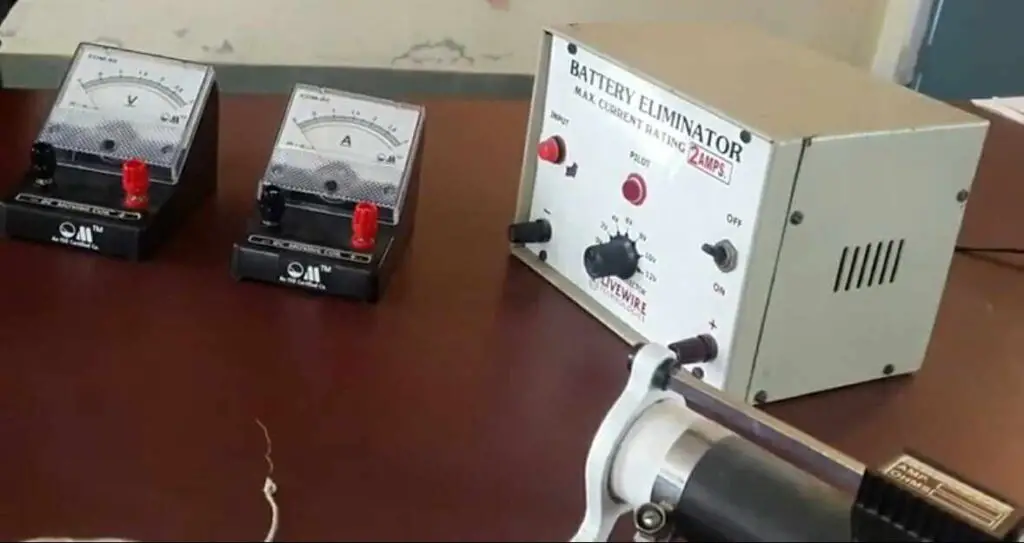
- A power supply (Voltage source or Battery): The used battery can supply the voltage from 0 to 12 volts.
- An Ammeter (A) to measure current. This Ammeter can measure the current from 0 to 3 amperes.
- A Voltmeter (V) to measure Voltage. The used Voltmeter can measure the voltage from 0 to 3 volts.
- A rheostat controls and adjusts the current through the circuit.
Circuit Diagram
Fig. (1) gives the circuit diagram for the verification of Ohm’s Law lab experiment.
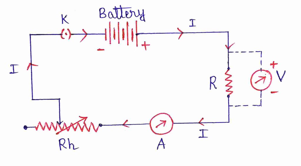
Here, R is the resistance of the wire, A is the ammeter, V is the Voltmeter, Rh is the rheostat and K is the key. The arrow sign indicates the direction of the current flow in the circuit .
Formula used for the Ohm’s law lab experiment
The formulae used for the Ohms law lab work are
\color{Blue}R = \frac{V}{I} ………….. (1) and \color{Blue}\rho = \frac{RA}{L} ………. (2)
Experimental data
The least count of Ammeter = Smallest division of Ammeter = 0.05 ampere
The least count of Voltmeter = Smallest division of voltmeter = 0.05 Volt
So, we can see that in each observation the voltage-to-current ratio is almost the same. Thus, the voltage across the wire is proportional to the current through the wire. Hence Ohm’s law is verified .
Now we got the calculated value of the resistance of the wire is R = 1.02 ohm.
We also need to plot I-V graph to confirm the experimental value of R.
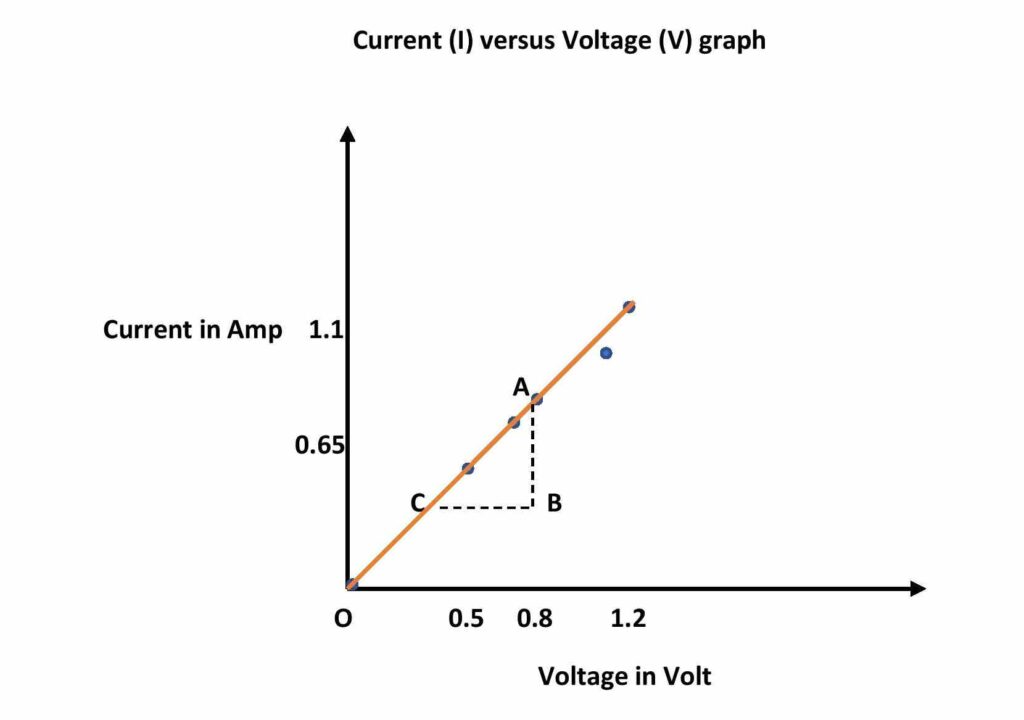
Current versus Voltage graph (Ohm’s Law graph)
If we plot the Current as a function of voltage with the help of the above data then we will get a straight line passing through the origin.
Calculations
Calculation of resistance from the graph.
The inverse of the I-V graph gives the resistance of the wire. Now, from the graph, change in current, ∆I = AB = 0.5 amp corresponding change in voltage, ∆V = BC = 0.5 volt Thus, the Resistance from the graph, R = ∆V/∆I = 0.5/0.5 = 1.00 ohm
Calculation of resistivity of the wire
Length of the wire is, L = 50 cm = 0.5 m Radius of the wire. r = 0.25 mm = 0.25 × 10 -3 m So, the cross-section area of the wire, A = πr 2 = 3.14 × (0.25×10 -3 ) 2 = 0.196 × 10 -6 m 2 Thus from the equation-2 we get the resistivity of the material of the wire is, \rho = (1 × 0.196 ×10 -6 )/0.5 or, \rho = 0.392 × 10 -6 = 3.92 ×10 -7 ohm.m Thus the resistivity of the material of the wire is 3.92 ×10 -7 ohm.m
Final result
The resistance of the wire from the Current-Voltage graph is, R = 1.00 ohm The calculated value of the resistance of the wire is, R = 1.02 ohm. Resistivity of the material of the wire is 3.92 ×10 -7 ohm.m
Discussions
- When the voltage V = 0, the reading of the ammeter is zero. That means the current through the wire is zero. Now, one cannot calculate the resistance for this data because one cannot measure the opposition faced by the current until the current flows.
- In the last two data, the current has not increased as much as first three observations. This is because of the increase in resistance of the wire due to heating. Here current flow through the wire causes joule’s heating.
- The calculated value of resistance almost matches the resistance calculated from the graph.
- If the radius (r) and length (L) of the wire are not supplied, then we have to determine those parameters by screw gauge and the meter scale respectively.
- In this experiment 1) verification of ohm’s law is done 2) Unknown resistance of the wire and 3) Resistivity of the material of the wire is determined.
This is all from this post on experimental verification of ohm’s law. If you find this post helpful, share it with your classmates and friends.
Related Posts:
- Ohm’s law and all facts
- Carbon resistor Color code
- Kirchhoff’s law (KCL and KVL)
- Electrical circuit components and their uses – Resistor, Capacitor, Inductor, Diode, Transistor
- Drift velocity of electrons
- Impedance formula (L, C, LC, RLC circuits)
5 thoughts on “Verification of Ohm’s Law experiment with data and graph”
- Pingback: Formula for Ohm's law of current and Voltage - Electronics & Physics
- Pingback: Kirchhoff's law of current and voltage (KCL & KVL) - Electronics & Physics
- Pingback: MCQ on current electricity for class 12 CBSE PDF - Electronics & Physics
- Pingback: Combination of resistors in series and parallel connection - edumir-Physics
- Pingback: Formula for impedance in electronics (RLC & LC circuit) - edumir-Physics
Comments are closed.

PhysicsTeacher.in
High School Physics + more
Ohm’s law statement with formula & VI Graph | derivation
Last updated on May 7th, 2021 at 04:19 pm

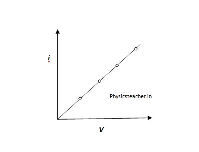
Ohm’s Law states : The potential drop across a resistor is proportional to the current passing through the resistor: V ∝ I. Ohm’s Law applies only to resistors with constant resistance ; that is, to resistors whose resistance is the same no matter what current is passing through them. For such resistors: V/I =R (where R is constant). Ohm’s Law can be written: V = IR (where R is constant). Resistors that obey Ohm’s Law are called ohmic resistors . For an ohmic resistor, the graph of V against I will be a straight line. The slope of the graph will equal the constant resistance. This is illustrated in figure 1. Any component that behaves like this is described as an ohmic component , and we say that it obeys Ohm’s law.
Look at the graph of Figure 1. Such a graph is known as an I–V characteristic . The points are slightly scattered in the graph shown, but they clearly lie on a straight line. A line of best fit has been drawn. You will see that it passes through the origin of the graph. In other words, the current I is directly proportional to the voltage V. The straight-line graph passing through the origin shows that the resistance of the conductor remains constant and it is independent of both the current and the p.d.
Here, in this post, we will discuss more on this and cover the following: Ohm’s Law, Statement, formula derivation, Verification of Ohm’s law with experiment, definition, calculation based on the formula, V-I graph of ohmic and non-ohmic conductors, etc.
- What is Ohm's Law?
- What is the formula for Ohm's law?
- How to derive Ohm's Law formula?
Draw the VI graph for Ohmic conductors
Ohmic conductors or ohmic resistor – features, draw the vi graph for conductors that behave non-ohmic as temperature rises, non-ohmic conductors or non-ohmic resistors – features, what we need for the experiment or verification test.
- Steps to execute Ohm's law experiment
- How to use Ohm's law formula to solve numerical problems
What is Ohm’s Law?
The potential drop across a resistor is proportional to the current passing through the resistor: V ∝ I. Ohm’s Law applies only to resistors with constant resistance; that is, to resistors whose resistance is the same no matter what current is passing through them. For such resistors: V/I =R (where R is constant). Ohm’s Law can be written: V = IR (where R is constant). In other words: Ohm’s law states that the current through a metallic element is proportional to the potential difference applied between its ends, provided the temperature remains constant. This statement is also known as Ohm’s Law Statement .
What is the formula for Ohm’s law?
The Ohm’s law formula is like this: V = IR , Here, V is the Potential difference across 2 ends of a conductor. And the symbol I denotes the current flowing through the conductor while R is the resistance of that conductor.
How to derive Ohm’s Law formula?
If a current I passes through a metallic element when a potential difference V is applied to that element (between its 2 ends), then we can write I ∝ V Here comes a proportionality constant (1/R) and the Ohm’s law equation becomes, I = (1/R) V => I = V/R or, V = IR ………………. (1) Here, Here R is a constant for the given element and is called its resistance. So, this law of Ohm can be expressed with the equation or formula, V = IR Thus, the derivation of Ohm’s law is done.
So we have seen that this law of Ohm can be expressed with the formula or equation, V = IR where V is the potential difference across the metallic element and I is the current flowing through the element. R is the electrical resistance of the element.
The following are equivalent statements of features about a certain type of resistor that follows Ohm’s law:
- the resistor is an ohmic resistor
- the resistor obeys Ohm’s Law
- the resistance of the resistor is constant
- the graph of V against I for the resistor is a straight line
- voltage is proportional to current for the resistor.
A device that follows Ohm’s law is said to be ohmic. In reality, no device is perfectly ohmic, though some materials follow approximately ohmic behavior for a wide range of currents. One reason conductors don’t remain ohmic is that their temperature rises as more current passes through them. The resistance of a normal conductor increases with increasing temperature, which makes it non-ohmic. An example of this non-ohmic conductor is the metal filament of an incandescent light , which gets quite hot under normal operation.

The following are equivalent statements about this type of non-ohmic resistor:
- the resistor is non-ohmic
- the resistor does not obey Ohm’s Law
- the resistance of the resistor is not constant
- the graph of V against I for the resistor is not a straight line.
How can we verify Ohm’s Law using an Experiment?
Here we will discuss how we can do an easy experiment to verify Ohm’s law.
What we need: Four or five dry cells, a thin wire (AB), a voltmeter, an ammeter, a plug key and some thick connecting wires.
Steps to execute Ohm’s law experiment
1> We have to start the test with a single cell. We have to connect the circuit as shown in Figure a. – The ammeter will show us the current I flowing through the circuit, and the voltmeter will measure the potential difference V between the ends A and B of the wire. – We have to note these values. (1st set of test data) Remember that this set of measured V and I are for a single cell setup.
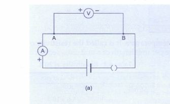
2> Now we have to connect two cells in series in the circuit, as shown in Figure b. – We will find that the reading of the voltmeter increases. This means that a larger potential difference has been applied across the wire AB. – This is obvious as we have in this case applied 2 cells in series. – We will also find that the reading of the ammeter has increased as well. We have to note down the new values of V and I. (2nd Set of test data)

3> We have to repeat the experiment by connecting in series three cells, four cells, and so on. In each case measure the potential difference and the current. (3rd Set, 4th Set….of test data) 4> If we calculate the value of V/I , for each test data set, we will find that it is almost the same. – So, V/I = R is a constant, which is another way of stating the law of Ohm. Here, R is the resistance of the wire AB. Ohm’s law graph: If we plot a graph of the current I against the potential difference V, it will be a straight line (Figure c). This shows that the current is proportional to the potential difference.

How to use Ohm’s law formula to solve numerical problems
Q: A 10 V battery is connected to a lamp of resistance 4 Ohm. calculate the current through the lamp. A: From the law of Ohm, current i = V/R =( 10 / 4 ) A = 2.5 A.
A means Ampere, unit of current. Now, Try the numerical sets here: Ohm’s Law based Numerical Problems – 3 worksheets
I hope you have liked this post on the law of Ohm. It’s a very interesting and important law of electricity chapter in Physics courses. This law also gives rise to the concept of Resistance. We have published a post on resistance and Numericals on Law of Ohm for high school students. Another relevant post is Series circuit, equivalent resistance and ohm’s law with solved numerical . Here is one post for parallel circuit as well.
Related Posts:
- j = sigma e derivation for the Vector form of Ohm's law
- Derivation of Ohm's Law class 12 (using drift velocity equations)
- Kirchhoff’s Voltage law, KVL - statement, formula, example, sign convention
- Limitations of Ohm’s Law
- How to use the VIR Triangle for Ohm's Law?
- Ohm's Law Problems in Physics - CBSE, ICSE Class 9 and 10
- Class 6 Maths
- Class 6 Science
- Class 6 Social Science
- Class 6 English
- Class 7 Maths
- Class 7 Science
- Class 7 Social Science
- Class 7 English
- Class 8 Maths
- Class 8 Science
- Class 8 Social Science
- Class 8 English
- Class 9 Maths
- Class 9 Science
- Class 9 Social Science
- Class 9 English
- Class 10 Maths
- Class 10 Science
- Class 10 Social Science
- Class 10 English
- Class 11 Maths
- Class 11 Computer Science (Python)
- Class 11 English
- Class 12 Maths
- Class 12 English
- Class 12 Economics
- Class 12 Accountancy
- Class 12 Physics
- Class 12 Chemistry
- Class 12 Biology
- Class 12 Computer Science (Python)
- Class 12 Physical Education
- GST and Accounting Course
- Excel Course
- Tally Course
- Finance and CMA Data Course
- Payroll Course
Interesting
- Learn English
- Learn Excel
- Learn Tally
- Learn GST (Goods and Services Tax)
- Learn Accounting and Finance
- GST Tax Invoice Format
- Accounts Tax Practical
- Tally Ledger List
- GSTR 2A - JSON to Excel
- NCERT Questions
- Questions from Inside the chapter
- Examples from NCERT Book
- Teachoo Questions
- MCQs from (Past Year Papers & NCERT Exemplar)
- Assertion Reasoning questions (MCQ)
- Case Based Questions (MCQ)
- Past Year - 1 Mark Questions
- Past Year - 2 Mark Questions
- Past Year - 3 Mark Questions
- Past Year - 5 Mark Questions
Experiment to Verify Ohm's Law
Last updated at Dec. 16, 2024 by Teachoo
Graphical Representation Volt and Amperes
Experiment to Verify Ohm's Law
We take a conductor (Example Nichrome Wire)
We connect it to a circuit containing Voltmeter and Ammeter
When we supply current, we measure reading of Potential Difference with the help of Voltmeter and Electric Current with help of Ammeter
We calculate Ratio of Potential Difference/Electric Current
Now,we increase amount of current,
We again measure reading of Potential Difference and Electric Current and again Calculate Ratio
We note that Ratio Remains the Same
Hence Ohm's Law, which states that Ratio of Potential Difference and Electric Current Remains the same, is verified

Q1. The values of Current (I) flowing through a conductor for the corresponding values of potential difference (V) are given. Plot a graph between V and I.

From the above table
We can see that,
the ratio of 𝑉/𝐼 is always constant.
This gives resistance
The resistance is 25 in above case

Q2. The values of Current (I) flowing through a conductor for the corresponding values of potential difference (V) are given. Plot a graph between V and I.

the ratio of V/I is always constant.
The resistance is 4 in above case

Q3. The values of Current (I) flowing through a conductor for the corresponding values of potential difference (V) are given. Plot a graph between V and I. Hence. find the resistance.

From the above table We can see that, the ratio of 𝑉/𝐼 is nearly constant. To find resistance, we find the mean of the resistances found. R = (3.2 + 3. 3 + 3.35 + 3.4 + 3.3)/5 R = 16.55/5 R = 3.31 Ω

Maninder Singh
CA Maninder Singh is a Chartered Accountant for the past 14 years and a teacher from the past 18 years. He teaches Science, Economics, Accounting and English at Teachoo
Hi, it looks like you're using AdBlock :(
Please login to view more pages. it's free :), solve all your doubts with teachoo black.
Learn all about Ohm's law
Ohm’s Law Lab Report [With Graph, Observations and Verification]
Ohm’s law is the fundamental law of Electrical Engineering. It relates the current flowing through any resistor to the voltage applied to its ends. According to the statement: The current flowing through a constant resistor is directly proportional to the voltage applied to its ends. This article presents the complete Ohm’s law Lab report and various questions regarding the lab. The latter portion simplifies the law for beginners by delineating the absolute basic concepts for beginners.
Objectives of Ohms Law Lab report
To verify that voltage and current are directly proportional using a 1kΩ resistor.
List of Components
- Variable DC Power supply
- 1kΩ resistor (Color code Brown, Black, Red, Gold)
- Connecting wires (Jumper wires)
Circuit Diagram
Setup the circuit diagram as shown below:
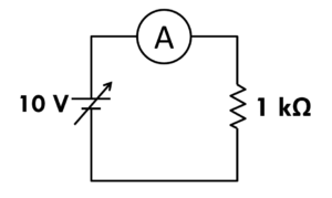
- Implement the circuit on the breadboard as shown in circuit diagram.
- Initially set the VDC supply to 0 V and note the current on ammeter.
- Increase the voltage to 1 V, observe the ammeter and note the readings.
- Repeat the above step for 2 V, 3V … 10 V.
- Plot a graph for measured readings.
- Compare the plot with theoretical calculations.
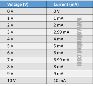
Observation table
Calculations [Verification of Ohm’s law report]
The theoretical calculations are achieved from the original formula, V = IR. You can also verify them from the basic Ohm’s law calculator .
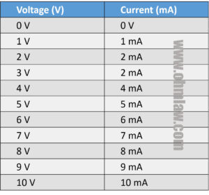
Graph for Ohm’s Law Lab report
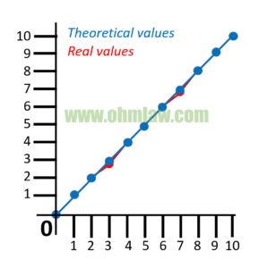
The real (practically calculated – red color) vs the theoretical values (blue) are plotted on the graph. While most theoretical values are identical to practical values, one might note a difference of red dot for 2.99 mA and 6.99 mA.
Conclusion from Ohm’s Law lab Report
We learned that current and voltage hold a direct relationship for resistive components. (They are linearly proportional).
Basic Questions for Ohm’s Law Lab Report
Question: What is Variable DC supply?
Answer: A variable DC (direct current) supply provides variable output voltages. It contains a rotary knob which can be rotated to achieve our desired output voltages. Its symbol is similar to dc battery with the difference of an arrowhead over it.
Question: What is ammeter?
Answer: It is the current measuring instrument which is used in series to the circuit. It measures current and displays the amperes on LCD.
Question: What is the resistor, and what is resistor color coding?
Answer: Resistor is an electrical component which is used to control the flow of electrical current. Carbon resistors are the most commonly available type of resistors. They have color bands over their bodies which are used to identify the amount of resistance they possess.
Question: What are jumper wires?
Answer: They are special types of wires which can be easily mounted and used on the breadboards.
Question: Is Ohm’s Law important to learn?
Answer: Yes Ohm’s law is a fundamental law of Electrical Engineering and it’s very important. You can easily learn each and everything about the law from our website.
Question: Why practical results are different from theoretical results?
Answer: While no scientific-practical can perfectly match the theory, the actual results depend on environmental conditions, the accuracy of equipment under test. The quality of resistor also impacts the measurements, while in our lab report we got excellent results, you might get different results based on your theory.
- ← Ohm’s Law Calculator
- 5 Error Sources in Ohm’s Law Experiment [How to avoid them] →
See Our New JEE Book on Amazon
Verification of Ohm's Law using Voltmeter and Ammeter
Ohm's law states that the current $I$ through a conductor is proportional to the voltage $V$ across its ends. It is written as $V=IR$, where $R$ is the resistance of the conductor.
Experiment to Verify Ohm's Law
Ohm's law can be easily verified in the lab or at home. You need a voltmeter, an ammeter, power supply (dry cells), resistors, and connecting wires. A simple procedure to verify Ohm's law is given below:
Take four or five dry cells, a thin wire (AB), a voltmeter, an ammeter, a plug key and some thick connecting wires. Connect the circuit as shown in figure, using one cell. The plug key allows you to switch off the current when not required. The wire becomes quite hot when current passes through it for some time. This drains the cell as well. Therefore, insert the key into the plug to switch on the current only when taking measurements.
The ammeter measures the current $I$ through the circuit, and the voltmeter measures the potential difference $V$ between the ends A and B of the wire. Note these values. Now, connect two cells in series in the circuit. You will find that the reading of the voltmeter increases, indicating the fact that a larger potential difference has been applied across the wire AB. You will also find that the reading of the ammeter increases as well. Note down the new values of $V$ and $I$. Repeat the experiment by connecting in series three cells, four cells, and so on. In each case measure the potential difference and the current. If you calculate $V/I$ for each case, you will find that it is almost the same. So, $V/I=R$ is a constant, which is another way of stating Ohm's law. Here, $R$ is resistance of the wire AB. If you plot a graph of the current of the current $I$ against the potential difference $V$, it will be a straight line. This shows that the current is proportional to the potential difference.
The experimental setup used in the laboratory makes use of a Rheostat to vary the potential difference $V$ across a standard resistor $R$.
Solved Problems on Verification of Ohm's Law
Problem on least count and zero error.
- (2 mA, 0.1 V) and (-2 mA, 0.2 V)
- (2 A, 0.1 V) and (-2 A, 0.2 V)
- (1 mA, 0.1 V) and (-1 mA, 0.2 V)
- (2 mA, 0.1 V) and (-2 mA, 0.1 V)
Solution: The least count of an instrument is the minimum value it can measure. It is the value of 1 division on the scale. For ammeter, 5 divisions are equal to 10 mA. Thus, the least count of the ammeter is 10/5=2 mA. For voltmeter, 10 divisions are equal to 1 V. Thus, the least count of the voltmeter is 1/10=0.1 V.
The zero error for the given ammeter is 1 division on the negative side which is equal to $-2$ mA. For voltmeter, zero error is 2 divisions on the positive side which is equal to 0.2 V.
Problem on Relative Error and Significant Figures
- $3.0 \Omega$
- $(3.0 \pm 0.2) \Omega$
- $(3 \pm 0.2) \Omega$
- $(3.0 \pm 0.1) \Omega$
Solution: From given data, the least count of the voltmeter is $\Delta V=0.01$ V and that of the ammeter is $\Delta I=0.1$ A. Ohm's law gives resistance as $R=V/I=4.20/1.4=3.0\;\mathrm{\Omega}$ (recall the rules of significant figures).
The relative error in resistance is \begin{align} \frac{\Delta R}{R}=\frac{\Delta V}{V}+\frac{\Delta I}{I}=0.07,\nonumber \end{align} which gives $\Delta R=0.2\,\mathrm{\Omega}$. Thus, the resistance should be reported as $(3.0 \pm 0.2) \Omega$.
Problem from IIT JEE 2003
Solution: The verification of Ohm's law ($V=IR$) requires the measurements of current through and voltage across the variable resistance. Hence answer is B.
Problem from IIT JEE 2004
Draw the circuit for experimental verification of Ohm's law using a source of variable DC voltage, a main resistance of $100\; \Omega$, two galvanometers and two resistances of values $10^6\; \Omega$ and $10^{-3}\;\Omega$, respectively. Clearly show the positions of the voltmeter and the ammeter.
Solution: Ohm's law verification requires measurement of the voltage and current. The galvanometer can be converted to a voltmeter by connecting a very high resistance (${10}^{6}\;\Omega$) in series and to an ammeter by connecting very low resistance ${10}^{-3}\; \Omega$) in parallel, as shown.
Problem from IIT JEE 2010
Solution: To verify Ohm's law, we need to measure voltage across the test resistance $R_T$ and current passing through it. The voltage can be measured by connecting high resistance $R_1$ in series with galvanometer. This combination becomes a voltmeter and shall be connected in parallel to $R_T$. The current can be measured by connecting low resistance $R_2$ in parallel with galvanometer. This combination becomes an ammeter and shall be connected in series to measure current through $R_T$. Hence answer is C.
Questions on Verification of Ohm's Law
Question 1: The internal resistance of the voltmeter is very high (ideal voltmeter has infinite resistance), whereas that of an ammeter is very low (ideal ammeter has zero resistance). The primary reason for this is A. The voltmeter is connected in series and ammeter is connected in parallel. B. The voltmeter is connected in parallel and ammeter is connected in series. C. The voltage and current that need to be measured should not get affected by the presence of voltmeter and ammeter in the circuit. D. The galvanometer is converted into a voltmeter by connecting very high resistance in series. It is converted to a voltmeter by connecting very low resistance in parallel.
Question 2: In an experiment to verify Ohm’s law, a student used a torch bulb as a resistor. When he plotted the voltage versus the current graph, he obtained a slightly curved line instead of the expected straight line. This may be due to A. variation in cell emf. B. temperature dependence of the bulb resistance. C. zero error in voltmeter or ammeter. D. non-ohmic nature of bulb material.
A Related Short Video by Dr HC Verma
Related topic.
- Significant Figures
- Metre Bridge | Experiment | Problems
References and External Links
- IIT JEE Physics by Jitender Singh and Shraddhesh Chaturvedi
- 100 Solved Problems on Units, Dimensions and Measurement, Jitender Singh and Shraddhesh Chaturvedi
- Concepts of Physics Part 2 by HC Verma (Link to Amazon)
- Amrita and CDAC, Online Labs
- NCERT Lab Manual for Class 12 (pdf)
- NCERT Lab Manual for Class 10 (pdf)


IMAGES
COMMENTS
Apr 20, 2021 · In the previous article, we discussed Ohm’s Law of current electricity. In this article, we’re going to perform an experiment for the verification of Ohm’s law. This practical verification of Ohm’s law is very important for the students of grades 10 and 12. This is a lab-based experiment to verify Ohm’s law or Ohm’s law practical.
Nov 3, 2019 · How can we verify Ohm’s Law using an Experiment? Here we will discuss how we can do an easy experiment to verify Ohm’s law. What we need for the Experiment or verification test . What we need: Four or five dry cells, a thin wire (AB), a voltmeter, an ammeter, a plug key and some thick connecting wires. Steps to execute Ohm’s law experiment
Feb 20, 2018 · Ohm performed repeated experiments on a resistor, applied different voltages, measured current and found relationship between these quantities. He finally published the law in 1827 and generalized his observations in single statement: The current flowing through the resistor is directly proportional to the voltage applied across it.
6 days ago · Hence Ohm's Law, which states that Ratio of Potential Difference and Electric Current Remains the same, is verified Q1. The values of Current (I) flowing through a conductor for the corresponding values of potential difference (V) are given. Plot a graph between V and I.
Feb 20, 2018 · He finally published the law in 1827 and generalized his observations in single statement: The current flowing through the resistor is directly proportional to the voltage applied across it. The website https://www.ohmlaw.com is a dedicated resource for Ohm’s law, calculation tools, applications and theoretical calculations on Ohm’s law.
80 Experiment 15: Ohm’s Law Advance Reading Text: Ohm’s Law, voltage, resistance, current. Lab Manual: Appendix B, Appendix C -DMM Objective The objective of this lab is to determine the resistance of several resistors by applying Ohm’s Law. Students will also be introduced to the resistor color code and refresh their graphing skills. Theory
The best graph plotted by a student for Ohm’s experiment is: Question 39: The given graph, is plotted for V-I to verify Ohm’s law. The resistance of the conductor used in the experiment is: (a) 1 Ω (b) 1.5 Ω (c) 3 Ω (d) 2 Ω. Question 40: A student wanted to make a battery of 6 V of cells with e.m.f 1.5 V each. The correct arrangement is ...
You will build a simple circuit, as illustrated in Figure 1, to experimentally verify Ohm's law which defines the mathematical relationship between resistance, voltage, and current. Figure 1. Test circuit for evaluating Ohm's law. Parts and Materials. 6 V battery; Assortment of resistors between 1 kΩ and 100 kΩ in value
The Experiment Part 1: 1. Look at several different resistors, which will be passed out to you. 2. There are two ways to find out what the value of any given resistor is. a. You can measure the resistance using the function marked Ω on your multi-meter. (kΩ means kilo-ohms or ohms x 1000. MΩ means mega-ohms or ohms x 1,000,000.)
Oct 22, 2019 · Solution: Ohm's law verification requires measurement of the voltage and current. The galvanometer can be converted to a voltmeter by connecting a very high resistance (${10}^{6}\;\Omega$) in series and to an ammeter by connecting very low resistance ${10}^{-3}\; \Omega$) in parallel, as shown.